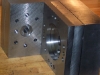
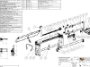
Combining block for plastic co-extrusion

Goal
A world class international manufacturer of specialty plastic film had successful production tooling that combined flows from two extruders for making 3 layer film. They wanted to duplicate the tooling and add two extruders to make 5 layer film.
Starting Point
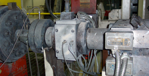
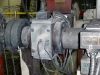
The manufacturer had old hand drawn prints used to make the original tooling overseas. They had a production line with a large main extruder and one smaller co-extruder for the outer layers. They wanted to prove the concept by building a new combining block and connecting it to the existing extruder prior to investing in 2 complete new additional extruders.
Features
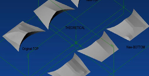
- Tooling measurement, analysis, and visual representation approach helped extrusion engineers define improved flow contours.
- New tooling improved flow distribution over existing design.
- New tooling allows more cost effective modification of combining performance through use of replaceable insert.
- New tooling successfully interfaced to precise connections to existing combining block, main melt pipes, co-extruder melt pipes and extrusion die.
Scope of work
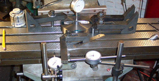
Acorn Meadow Designs first used CMM data obtained by the manufacturer of two existing tools and compared that to theoretical forms from the old tooling prints. Aided by AMD’s analysis and visual representation of results, the manufacturer’s polymer engineers determined how the shape should be modified to obtain their desired layer uniformity.
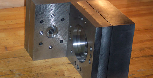
AMD reverse engineered the precision multi part tooling, adding new features such as an easily replaceable flow insert which contained the important flow distribution contour. AMD engineered a new external manifold to split the flow of the existing small extruder to supply the new combining block as well as the old block to simulate the existence of the proposed new extruders. All design work was done in a solid modeling environment. The tooling was built by AMD sub-contractors and extensively measured for resulting flow contour confirmation.
The manufacturer installed and tested the tooling and found improved distribution over the old tooling. Distribution still needed to be more uniform so a second insert with modified flow contours was designed and built. This insert resulted in significantly more uniform flow distribution and was so satisfactory that it replaced the tooling that had been in production for years. Procurement and installation of the additional new extruders is now on going.
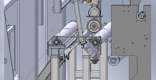
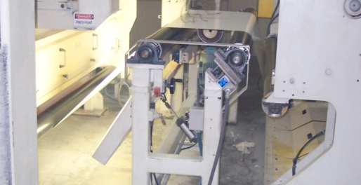
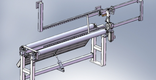
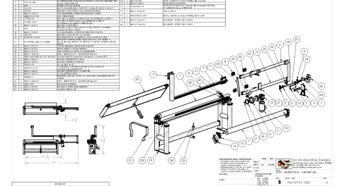
Center Slit Station
Goal
Engineer a center slit station to retro-fit into a film line during a planned shut-down for other upgrades.
Starting Point
The existing production line was in full production. A few hardcopy general layout drawings were available, no detail drawings. Plant wanted a wider station with easy thread-up, easy blade changing and high quality edges. Existing load cell roll for tension monitoring was to be re-used.
Features
- Station to allow safe and fast thread-up near operating line speeds.
- Operators never let go of web while threading station.
- Web path idler rolls under web supported from below.
- Web path rolls that web passed under supported from over-head.
- Slitter knife moves well away from web if web breaks and during thread-up.
- High quality accurate slit edges very important for this premium product.
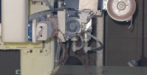
- Tidland Class II knife holder holds blade at optimum angle and pressure against driven anvil knife.
- Sub-frame holding both upper and lower knife together can be manually fine adjusted from operator aisle while running to keep slit correctly located.
- Lower anvil knife independently driven to optimize speed for best edge quality.
- Station designed for high productivity and easy maintenance.
- Both blades can be changed while line is running.
- Sub-frame holding upper and lower blades mounts on precision linear rails for removal to side of line for safe convenient service without stopping the line.
- Setting blade cant angle and other shearing adjustments can be made while line is running.
- Retrofit station designed for quick installation during limited line shut down window.
- Sub-frame required mounting to existing machine structure with welding and match drilling. Station was shipped with temporary alignment jig bolted in place to keep top mounted sub-frame spaced correctly to floor mounted base frame during installation.
- To minimize cost existing load cells were reconfigured for use on new replacement station.